Try to imagine automated industrial production line in the sixties and seventies. There was always a huge electrical board for system controls, and not infrequently it covered an entire wall! Within this board there was a great number of interconnected electromechanical relays to make the whole system work. By word "connected" it was understood that electrician had to connect all relays manually using wires! An engineer would design logic for a system, and electricians would receive a schematic outline of logic that they had to implement with relays. These relay schemas often contained hundreds of relays. The plan that electrician was given was called "ladder schematic". Ladder displayed all switches, sensors, motors, valves, relays, etc. found in the system. Electrician's job was to connect them all together. One of the problems with this type of control was that it was based on mechanical relays. Mechanical instruments were usually the weakest connection in the system due to their moveable parts that could wear out. If one relay stopped working, electrician would have to examine an entire system (system would be out until a cause of the problem was found and corrected).
The other problem with this type of control was in the system's break period when a system had to be turned off, so connections could be made on the electrical board. If a firm decided to change the order of operations (make even a small change), it would turn out to be a major expense and a loss of production time until a system was functional again.
It's not hard to imagine an engineer who makes a few small errors during his project. It is also conceivable that electrician has made a few mistakes in connecting the system. Finally, you can also imagine having a few bad components. The only way to see if everything is all right is to run the system. As systems are usually not perfect with a first try, finding errors was an arduous process. You should also keep in mind that a product could not be made during these corrections and changes in connections. System had to be literally disabled before changes were to be performed. That meant that the entire production staff in that line of production was out of work until the system was fixed up again. Only when electrician was done finding errors and repairing,, the system was ready for production. Expenditures for this kind of work were too great even for well-to-do companies.
First Programmable Logic Controllers ( PLC )
"General Motors" is among the first who recognized a need to replace the system's "wired" control board. Increased competition forced auto-makers to improve production quality and productivity. Flexibility and fast and easy change of automated lines of production became crucial! General Motors' idea was to use for system logic one of the microcomputers (these microcomputers were as far as their strength beneath today's eight-bit microcontrollers) instead of wired relays. Computer could take place of huge, expensive, inflexible wired control boards. If changes were needed in system logic or in order of operations, program in a microcomputer could be changed instead of rewiring of relays. Imagine only what elimination of the entire period needed for changes in wiring meant then. Today, such thinking is but common, then it was revolutionary!
Everything was well thought out, but then a new problem came up of how to make electricians accept and use a new device. Systems are often quite complex and require complex programming. It was out of question to ask electricians to learn and use computer language in addition to other job duties. General Motors Hidromatic Division of this big company recognized a need and wrote out project criteria for first programmable logic controller ( there were companies which sold instruments that performed industrial control, but those were simple sequential controllers û not PLC controllers as we know them today). Specifications required that a new device be based on electronic instead of mechanical parts, to have flexibility of a computer, to function in industrial environment (vibrations, heat, dust, etc.) and have a capability of being reprogrammed and used for other tasks. The last criteria was also the most important, and a new device had to be programmed easily and maintained by electricians and technicians. When the specification was done, General Motors looked for interested companies, and encouraged them to develop a device that would meet the specifications for this project.
"Gould Modicon" developed a first device which met these specifications. The key to success with a new device was that for its programming you didn't have to learn a new programming language. It was programmed so that same language ûa ladder diagram, already known to technicians was used. Electricians and technicians could very easily understand these new devices because the logic looked similar to old logic that they were used to working with. Thus they didn't have to learn a new programming language which (obviously) proved to be a good move. PLC controllers were initially called PC controllers (programmable controllers). This caused a small confusion when Personal Computers appeared. To avoid confusion, a designation PC was left to computers, and programmable controllers became programmable logic controllers. First PLC controllers were simple devices. They connected inputs such as switches, digital sensors, etc., and based on internal logic they turned output devices on or off. When they first came up, they were not quite suitable for complicated controls such as temperature, position, pressure, etc. However, throughout years, makers of PLC controllers added numerous features and improvements. Today's PLC controller can handle highly complex tasks such as position control, various regulations and other complex applications. The speed of work and easiness of programming were also improved. Also, modules for special purposes were developed, like communication modules for connecting several PLC controllers to the net. Today it is difficult to imagine a task that could not be handled by a PLC.
Components of Programmable Logic Controllers ( PLC )
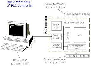
PLC is actually an industrial microcontroller system (in more recent times we meet processors instead of microcontrollers) where you have hardware and software specifically adapted to industrial environment. Block schema with typical components which PLC consists of is found in the following picture. Special attention needs to be given to input and output, because in these blocks you find protection needed in isolating a CPU blocks from damaging influences that industrial environment can bring to a CPU via input lines. Program unit is usually a computer used for writing a program (often in ladder diagram).
Central Processing Unit – CPU of Programmable Logic Controllers ( PLC )
Central Processing Unit (CPU) is the brain of a PLC controller. CPU itself is usually one of the microcontrollers. Aforetime these were 8-bit microcontrollers such as 8051, and now these are 16- and 32-bit microcontrollers. Unspoken rule is that you'll find mostly Hitachi and Fujicu microcontrollers in PLC controllers by Japanese makers, Siemens in European controllers, and Motorola microcontrollers in American ones. CPU also takes care of communication, interconnectedness among other parts of PLC controller, program execution, memory operation, overseeing input and setting up of an output. PLC controllers have complex routines for memory checkup in order to ensure that PLC memory was not damaged (memory checkup is done for safety reasons). Generally speaking, CPU unit makes a great number of check-ups of the PLC controller itself so eventual errors would be discovered early. You can simply look at any PLC controller and see that there are several indicators in the form of light diodes for error signalization.

Memory of Programmable Logic Controllers ( PLC )
System memory (today mostly implemented in FLASH technology) is used by a PLC for an process control system. Aside from this operating system it also contains a user program translated from a ladder diagram to a binary form. FLASH memory contents can be changed only in case where user program is being changed. PLC controllers were used earlier instead of FLASH memory and have had EPROM memory instead of FLASH memory which had to be erased with UV lamp and programmed on programmers. With the use of FLASH technology this process was greatly shortened. Reprogramming a program memory is done through a serial cable in a program for application development.
User memory is divided into blocks having special functions. Some parts of a memory are used for storing input and output status. The real status of an input is stored either as "1" or as "0" in a specific memory bit. Each input or output has one corresponding bit in memory. Other parts of memory are used to store variable contents for variables used in user program. For example, timer value, or counter value would be stored in this part of the memory.
Programming of Programmable Logic Controllers ( PLC )
PLC controller can be reprogrammed through a computer (usual way), but also through manual programmers (consoles). This practically means that each PLC controller can programmed through a computer if you have the software needed for programming. Today's transmission computers are ideal for reprogramming a PLC controller in factory itself. This is of great importance to industry. Once the system is corrected, it is also important to read the right program into a PLC again. It is also good to check from time to time whether program in a PLC has not changed. This helps to avoid hazardous situations in factory rooms (some automakers have established communication networks which regularly check programs in PLC controllers to ensure execution only of good programs).
Almost every program for programming a PLC controller possesses various useful options such as: forced switching on and off of the system inputs/ouputs (I/O lines), program follow up in real time as well as documenting a diagram. This documenting is necessary to understand and define failures and malfunctions. Programmer can add remarks, names of input or output devices, and comments that can be useful when finding errors, or with system maintenance. Adding comments and remarks enables any technician (and not just a person who developed the system) to understand a ladder diagram right away. Comments and remarks can even quote precisely part numbers if replacements would be needed. This would speed up a repair of any problems that come up due to bad parts. The old way was such that a person who developed a system had protection on the program, so nobody aside from this person could understand how it was done. Correctly documented ladder diagram allows any technician to understand thoroughly how system functions.
Power supply of Programmable Logic Controllers ( PLC )
Electrical supply is used in bringing electrical energy to central processing unit. Most PLC controllers work either at 24 VDC or 220 VAC. On some PLC controllers you'll find electrical supply as a separate module. Those are usually bigger PLC controllers, while small and medium series already contain the supply module. User has to determine how much current to take from I/O module to ensure that electrical supply provides appropriate amount of current. Different types of modules use different amounts of electrical current.
This electrical supply is usually not used to start external inputs or outputs. User has to provide separate supplies in starting PLC controller inputs or outputs because then you can ensure so called "pure" supply for the PLC controller. With pure supply we mean supply where industrial environment can not affect it damagingly. Some of the smaller PLC controllers supply their inputs with voltage from a small supply source already incorporated into a PLC.
Inputs of Programmable Logic Controllers ( PLC )
Intelligence of an automated system depends largely on the ability of a PLC controller to read signals from different types of sensors and input devices. Keys, keyboards and by functional switches are a basis for man versus machine relationship. On the other hand, in order to detect a working piece, view a mechanism in motion, check pressure or fluid level you need specific automatic devices such as proximity sensors, marginal switches, photoelectric sensors, level sensors, etc. Thus, input signals can be logical (on/off) or analogue. Smaller PLC controllers usually have only digital input lines while larger also accept analogue inputs through special units attached to PLC controller. One of the most frequent analogue signals are a current signal of 4 to 20 mA and milivolt voltage signal generated by various sensors. Sensors are usually used as inputs for PLCs. You can obtain sensors for different purposes. They can sense presence of some parts, measure temperature, pressure, or some other physical dimension, etc. (ex. inductive sensors can register metal objects).
Other devices also can serve as inputs to PLC controller. Intelligent devices such as robots, video systems, etc. often are capable of sending signals to PLC controller input modules (robot, for instance, can send a signal to PLC controller input as information when it has finished moving an object from one place to the other.)
Input adjustment interface of Programmable Logic Controllers ( PLC )
Adjustment interface also called an interface is placed between input lines and a CPU unit. The purpose of adjustment interface to protect a CPU from disproportionate signals from an outside world. Input adjustment module turns a level of real logic to a level that suits CPU unit (ex. input from a sensor which works on 24 VDC must be converted to a signal of 5 VDC in order for a CPU to be able to process it). This is typically done through opto-isolation, and this function you can view in the following picture. Opto-isolation means that there is no electrical connection between external world and CPU unit. They are "optically" separated, or in other words, signal is transmitted through light. The way this works is simple. External device brings a signal which turns LED on, whose light in turn incites photo transistor which in turn starts conducting, and a CPU sees this as logic zero (supply between collector and transmitter falls under 1V). When input signal stops LED diode turns off, transistor stops conducting, collector voltage increases, and CPU receives logic 1 as information.

Output of Programmable Logic Controllers ( PLC )
Automated system is incomplete if it is not connected with some output devices. Some of the most frequently used devices are motors, solenoids, relays, indicators, sound signalization and similar. By starting a motor, or a relay, PLC can manage or control a simple system such as system for sorting products all the way up to complex systems such as service system for positioning head of CNC machine. Output can be of analogue or digital type. Digital output signal works as a switch; it connects and disconnects line. Analogue output is used to generate the analogue signal (ex. motor whose speed is controlled by a voltage that corresponds to a desired speed).
Output adjustment interface of Programmable Logic Controllers ( PLC )
Output interface is similar to input interface. CPU brings a signal to LED diode and turns it on. Light incites a photo transistor which begins to conduct electricity, and thus the voltage between collector and emmiter falls to 0.7V , and a device attached to this output sees this as a logic zero. Inversely it means that a signal at the output exists and is interpreted as logic one. Photo transistor is not directly connected to a PLC controller output. Between photo transistor and an output usually there is a relay or a stronger transistor capable of interrupting stronger signals.

Extension lines of Programmable Logic Controllers ( PLC )
Every PLC controller has a limited number of input/output lines. If needed this number can be increased through certain additional modules by system extension through extension lines. Each module can contain extension both of input and output lines. Also, extension modules can have inputs and outputs of a different nature from those on the PLC controller (ex. in case relay outputs are on a controller, transistor outputs can be on an extension module).
PLC controller output lines
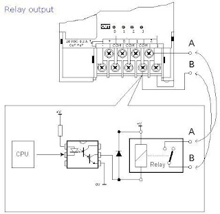
Aside from transistor outputs in PNP and NPN connections, PLC can also have relays as outputs. Existence of relays as outputs makes it easier to connect with external devices. There a 4 relays whose functional contacts are taken out on a PLC controller housing in the form of screw terminals. In reality this looks as in picture below.


PLC controller input lines
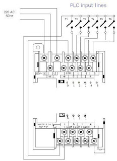
Different sensors, keys, switches and other elements that can change status of a joined bit at PLC input can be hooked up to the PLC controller inputs. In order to realize a change, we need a voltage source to incite an input. The simplest possible input would be a common key. Source of direct voltage of 24V, the same source can be used to incite input (problem with this source is its maximum current which it can give continually and which in our case amounts to 0.2A). Since inputs to a PLC are not big consumers (unlike some sensor where a stronger external supply must be used) it is possible to take advantage of the existing source of direct supply to incite all six keys.

author: Nebojsa Matic
2 Response to "Introduction to Programmable Logic Controllers"
You can find more information on PLC Programming & Instrumentation here
Website: www.InstrumentationTools.com
Thanks for sharing such great information with us and I hope u will share some more information about PLC and its compnents process input and outputs in industrial automation field. This information is very useful for me to increase my knowledge Please keep sharing.
PLC SCADA Automation Training Institute in Thane, Mumbai
Post a Comment